|
|  |
| TV-LINK |
The TV-Link is a device that allows the player to connect his/her Supervision
to a television screen in order to play games on a larger display. A blue
border surrounds the game screen. The TV-Link predates Nintendo's Super Game
Boy, a product which provides a similar experience.
A different color palette is applied to the games when they are used with the
TV-Link. The result, in popular opinion, actually looks worse than the Supervision's
own LCD display. Some games also have speed, sound and/or display issues when
used with the device.
Though a full range of different colors can be projected from the TV-Link
through clever programming, none of the officially released games exploit
this “feature.” Two different models of the TV-Link were produced:
PAL and NTSC. The colors are accessed differently between models.
As illustrated in the instructions, the TV-Link was designed for use with
the “bendable” versions of the Supervision. However it will also
work with the other versions (sans the Magnum) albeit with slight changes
in performance.
When the TV-Link and the Supervision inside it are both powered on, the
Supervision's LCD screen displays the following graphic:
   |
| |
P H O T O S | |
| |
I N S T R U C T I O N S |
SECTION 1
SUPERVISION TV-LINK FEATURES
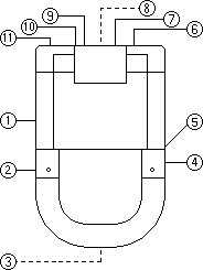
(A) TV-LINK
| 1. |
Power Switch (Power) |
| 2. |
Power-On Indicator |
| 3. |
Slot for game cartridge insertion |
| 4. |
Low-Battery Indicator |
| 5. |
Two-Player Link (comm. port) |
| 6. |
Socket (connect to SUPERVISION
CONNECTION CARTRIDGE) |
| 7. |
External Power Supply Jack |
| 8. |
Battery Cover (back) | |
| 9. |
Audio Output |
| 10. |
Video Output |
| 11. |
RF Output (connect to television set) |
|
|  |
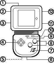
(B) SUPERVISION (Not included in SUPERVISION TV-LINK package)
| 1. |
Power Switch (POWER) |
| 2. |
External Power Supply Jack |
| 3. |
Contrast Adjustment (CONTRAST) |
| 4. |
Direction Buttons |
| 5. |
Battery Cover (back) |
| 6. |
Headphones Jack (PHONES) |
| 7. |
Speaker |
| 8. |
A" & "B" Buttons - | Please refer the game
cartridges instruction. |
| 9. |
Select Buttons |
| 10. |
Start Buttons |
| 11. |
Volume Dial (VOLUME) |
| 12. |
Two Player Link (comm. port) |
|
|  |
(C) OTHER ACCESSORIES
| a. TV CABLE |
|
| 1. |
Plug (connect to SUPERVISION TV-LINK / SWITCHING BOX) |
|
|  |
| b. SUPERVISION CONNECTION CARTRIDGE |
|
| 1. |
Plug (connect to SUPERVISION TV-LINK) |
| 2. |
TV-LINK ADAPTOR cartridge (connect to SUPERVISION) |
| 3. |
DC Plug (connect to SUPERVISION DC 6V input when using AC-DC Adaptor) |
|
|  |
| c. VIDEO SWITCHING BOX |
|
| 1. |
Connect to TV-LINK |
| 2. |
Selection Switch (TV-LINK / TV Program) |
| 3. |
Connect to ANTENNA INPUT of television set |
| 4. |
Connect to ANTENNA |
|
| |

| d. AUDIO/VIDEO CABLE |
|
| 1. |
White Plug
(connect to TV-LINK Audio Output/Television Set Audio Input) |
| 2. |
Yellow Plug
(connect to TV-LINK Video Output/Television Set Video Input) |
|
|  |
SECTION 2
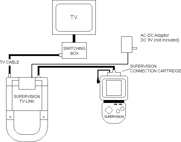
SUPERVISION TV-LINK CONNECTION
(A) USING RF-OUTPUT
 (B) USING VIDEO/AUDIO OUTPUT
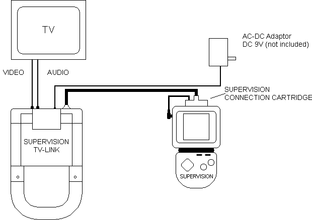 SECTION 3
NOTE FOR BATTERY-USER
| • |
Remove the cover on the back of the SUPERVISION and SUPERVISION TV-LINK and insert four "AA" batteries in each machine. |
| • |
Make sure that the batteries, plus (+) and minus (-) ends are facing the right directions. |
| • |
Do not use rechargeable batteries. |
| • |
Do not use mercury oxide batteries. |
| • |
For best results, use alkaline batteries. |
| • |
Do not connect the DC plug to SUPERVISION (Section 1, Part C, Point b3). |
SECTION 4
HOW TO OPERATE
| 1. |
For Battery Users, make sure that BATTERIES have been installed. |
| 2. |
For AC-DC Adaptor Users, connect DC Plug (from SUPERVISION CONNECTION CARTRIDGE) to the SUPERVISION DC 6V Input. Connect AC-DC Adaptor to the External Power Supply Jack (Section 1, Part A, Point 7) of the SUPERVISION TV-LINK. |
| 3. |
Connect SUPERVISION TV-LINK to SUPERVISION by SUPERVISION CONNECTION CARTRIDGE. |
| 4. |
Connect SUPERVISION TV-LINK to TV-Set with the use of the SWITCHING BOX. Set the switch of the SWITCHING BOX to GAME. (See SECTION 2 for detailed illustration of SUPERVISION TV-LINK connection.) Remarks: Player can watch television without removing the SUPERVISION TV-LINK connection by setting the switch of the SWITCHING BOX to TV. |
| 5. |
For A/V Output Users, connect the Audio and Video Cable between the TV-Set and the TV-LINK according to Section 2. |
| 6. |
Insert a game cartridge into the SUPERVISION TV-LINK slot. |
| 7. |
Turn on SUPERVISION TV-LINK. |
| 8. |
Turn on SUPERVISION. |
| 9. |
Tilt the screen of SUPERVISION and place SUPERVISION on SUPERVISION TV-LINK. |
IMPORTANT NOTICE
| • |
When changing a game cartridge, make sure that the power is turned "OFF". |
| • |
When inserting a game cartridge into the SUPERVISION TV-LINK slot, please make sure that the side with the LABEL faces down. |
SECTION 5
| FAULT |
SUGGESTED ACTION |
| | The Power-On LED is dark. |
|
| • | For battery user: replace batteries. | | • | For AC-DC Adaptor user: check that the DC polarity of the adaptor is correct. |
|
| | No sound can be heard during the game. |
|
| • | Check that the game cartridge is inserted properly. | | • | Adjust TV-Set Volume. |
|
| No picture on TV-Set. |
| • | Select suitable channel on TV-Set, e.g. A/V, Television Channel. |
|
| | No display on SUPERVISION screen. |
|
| • | Check that the SUPERVISION CONNECTION CARTRIDGE is inserted properly. | | • | Check power supply. |
|
| The Low-Battery LED is lit. |
• Replace TV-Link batteries. |
|
| |